Design Brief: Glulam Beam Design

Curious about mass timber? Let's start at the beginning with the humble glulam beam - the absolute cornerstone of modern mass timber design in today's world. Glulam beams are generally made up of commonly available light-frame 2x lumber that's glued together, hence glued-laminated (glulam). We include a copy of our glulam beam sample calculation as a part of every copy of Stride to help you get started quickly - and right now, we'll go over how we created a simple design for that with Stride.
Design brief
Let's assume you're at the start of a project and the architect lets you know that they're thinking about 30' by 30' modular bays with a basic 3ply CLT (Cross Laminated Timber) panel and glulam purlin/girder/column layout. Something like the following plan.
Your boss, being quite savvy herself, already has a size in mind for the purlins, but wants you to make some calcs to double check and to start documenting your designs for the calculation package down the line.
Material specifics
As the architects are looking to expose the mass timber elements, they want to use Douglas Fir consistently throughout the project. Because of that, you flip through the NDS Supplement and look for the grade of beam that would be appropriate for this design. You end up selecting DF/DF 24F-V4 from Table 5A as:
- DF (Douglas Fir) is your required material choice,
- 24F (the bending strength grade) for the cost and the availability, and
- V4 (to determine the layup) as these purlins will only experience tension on the bottom laminations (negative bending only).
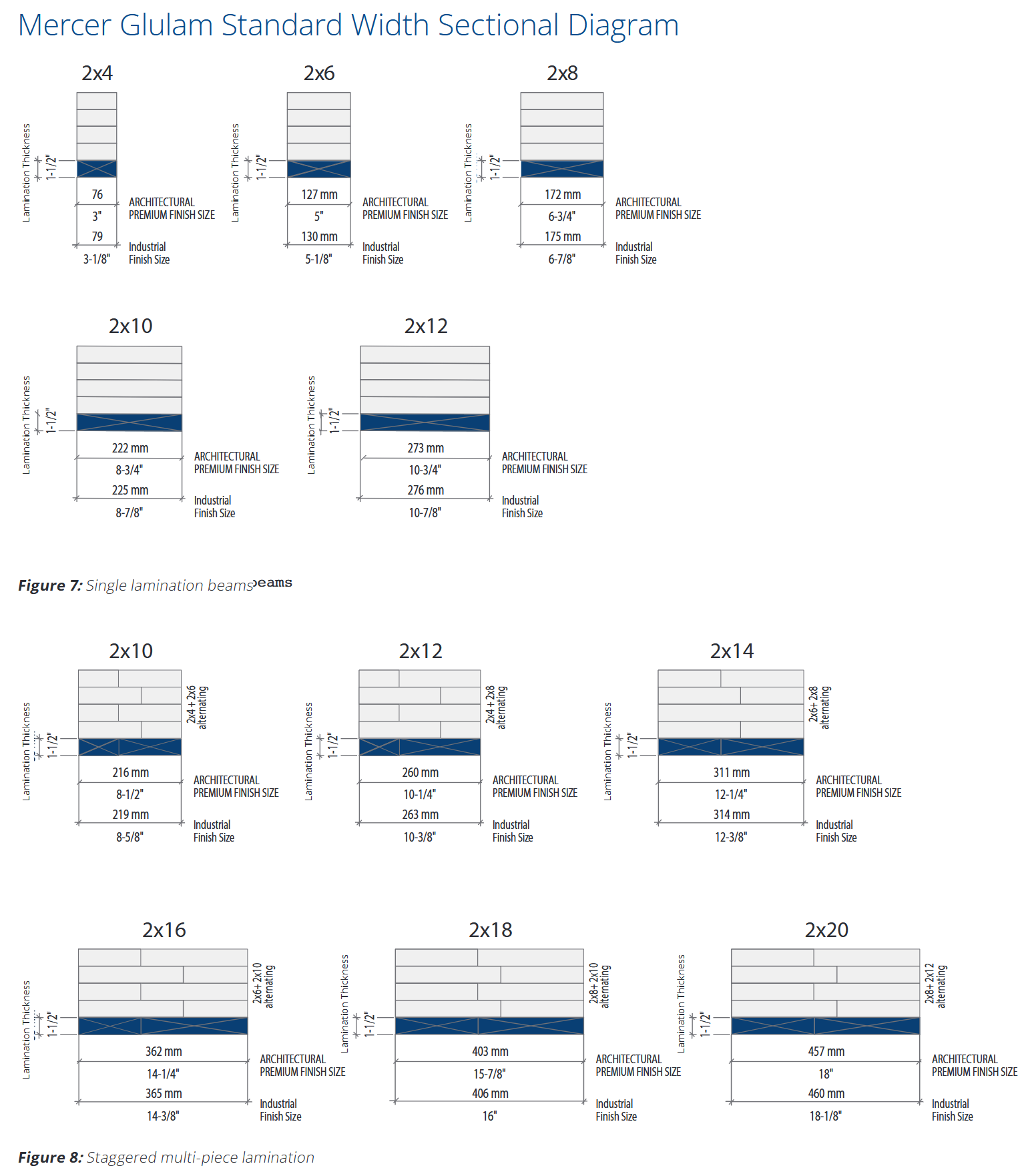
For sizing glulam beams, you also remember that generally, the wood is comprised of glued up pieces of 2x lumber (like 2x4's and 2x8's), so layups are generally 1.5” thick. Take Mercer's glulam beam catalogue for example.

Source: Mercer Mass Timber Design Guide
Later on, you'll also need to figure out things like fire ratings, char depths, notches, penetrations, moisture impacts, and other design elements, but for now, let's keep it simple. The calculation sheet you'll make should be easy to review and understand, but also easy to change and adapt for future use!
Loading conditions
Overall, you don't have a lot of information as to the exact loading conditions due to the early stage of the project, so you make some assumptions that can help cover you down the line and get started!
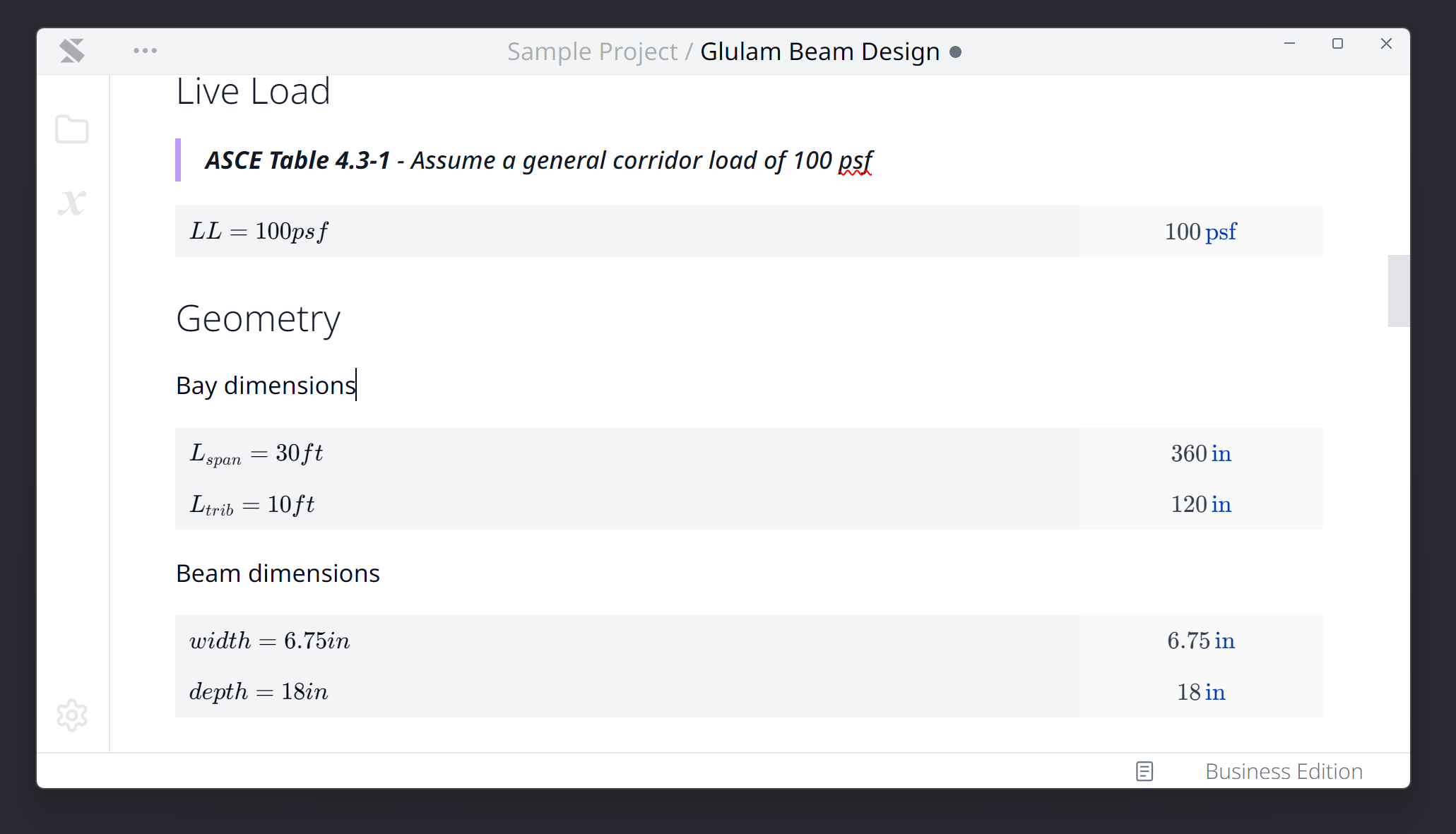
Since you don't know what the specific use case these beams will support, you assume a general corridor load for the live load.
Geometry
The loading geometry itself is pretty simple. As the bay is tiled 30' x 30' square, each purlin spans 30' and has a 10' tributary width.

Since this is the first pass, you just pick a random size matching the combination from a manufacturer's catalogue (see above for Mercer's) and hope it works. Let's say… 6.75” x 18”. So that's basically 2x8 pieces with 12 laminations. Cool.
Material Properties
Since you've already chosen the material itself, grabbing the properties from the same table from the Supplement is pretty easy.
Calculation
Now that you have all the required inputs, it's time to crack open NDS 2024, turn to Chapter 5 and actually carry out the design check.
Adjustment Factors
In calculating the adjustment factors, Table 5.3.1 is an absolute godsend in understanding what to apply to what type of check you are doing. In this simplified, early stage analysis, you set most of the other factors to 1 except for the volume factor.
The volume factor is this long, messy equation, with units built in. But you know that if you just ensure that you enter the equation in with the right set of units (so that they cancel out), the equation then becomes unit agnostic and can be used with any unit.
Loads and Resistances
At last, you then calculate out the factored resistances and factored loads to find if the beam is ok or not! Don't forget to include a DCR check at the top so that you can easily see that this is passing.
Iterating to the final design
Yikes! So it seems that from a strength perspective, it's still not quite working with a bending utilization ratio of 200%! But now comes the easy part. You just go up to where you defined the width and depth, change those to something 8.75” x 24” (2x10 with 16 laminations), and immediately see that the DCR has now dropped to 89%. Fantastic.
Now, you go up to the top, add a quick todo list for calculating the deflection/connections and then reward yourself with a well deserved coffee break for hammering out a clear, reusable, and easily updatable glulam beam calculation in 15 minutes. Well done!
Summary
And that's the first step in our journey to become mass timber experts! To recap, we
- Set out the design parameters
- Figured out the geometry and loading criteria
- Selected the material and adjustment factors
- Calculated the loads and resistances
- And then iterated to the final design
See you next time!